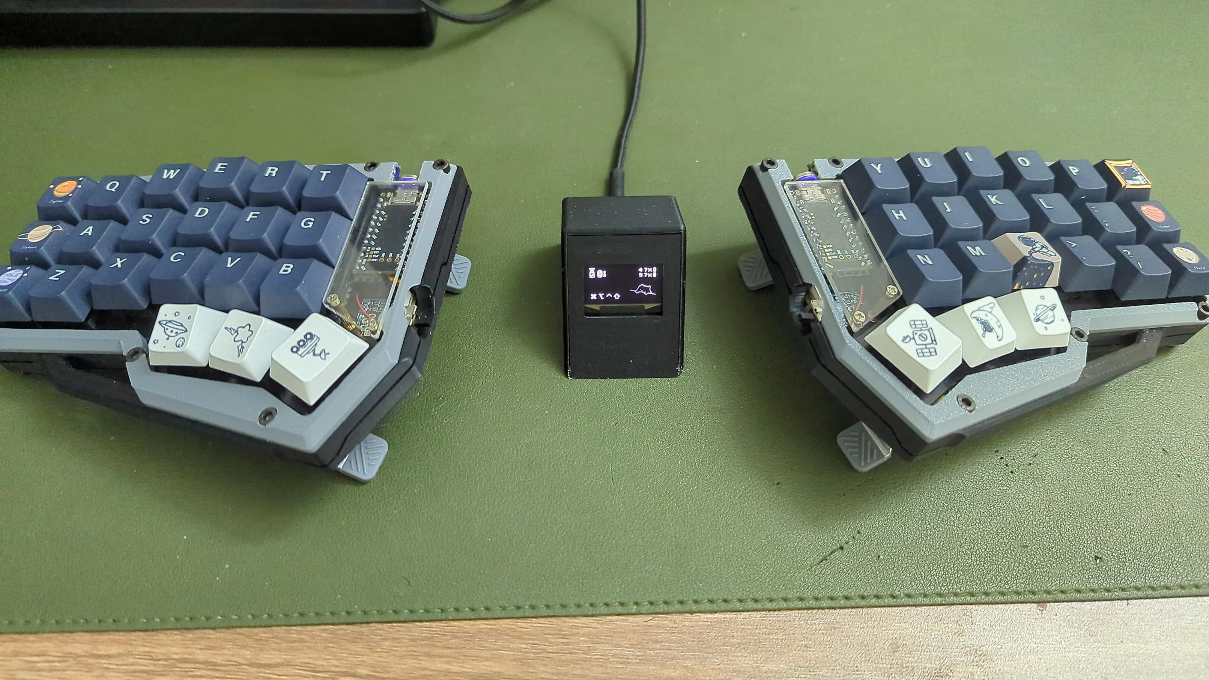
How I made my wired Corne Keyboard wireless
Hello there!
It’s been a while since I’ve update this blog huh. But hey, I’m back with new content!
The Premise
I’ve gotten into keyboard stuff lately, especially DIY ergonomic keyboards and the likes, so I bought a Corne Classic keyboard kit, follow some tutorial online, and voila, an ergonomic keeb!!!
So the way the Corne Classic works is that there are 2 halves, the left side (master) is connected to the computer, sending the signal via USB-C cable, the right side (peripheral) is connected to the master by a TRRS-to-TRRS cable (TRS-to-TRS is fine too), then the signal is send to the PC via the master side.
Now there’s the problem, since the keyboard is wired, it’s placement is limited by the length of the TRRS cable, as well as the USB-C cable. What would be the solution then? Bluetooth of course!
Preparation
Here’s a list of what I bought to make this happen:
- 3x SuperMini NRF52840 (I got 3 since I want to make a dongle, you only need 2)
- 2x 401230 Li-Po batteries (I want to get the 301230 batteries, but sadly I couldn’t find any place that sell them in Vietnam)
- 2x 3-pronges switches (optional, but recommended to physically turn off the keyboard if you want to travel with your keyboard)
- 1x 0.96 inches 128x64 oled screen (optional, to be used with the dongle)
- 2x Nice!View displays (optional, the shop selling this ran out of stock so I’m gonna update this part later)
- 1x 3D-printed case (optional, to be used with the dongle, I use this case)
The Keyboard
So right at the beginning, we have an issue: the Corne Classic pcb doesn’t support battery connection with a physical switch.
I struggled to find a comprehensive guide for this, but after screwing around Reddit and Discord for a while, I finally found out how to achieve my goal.
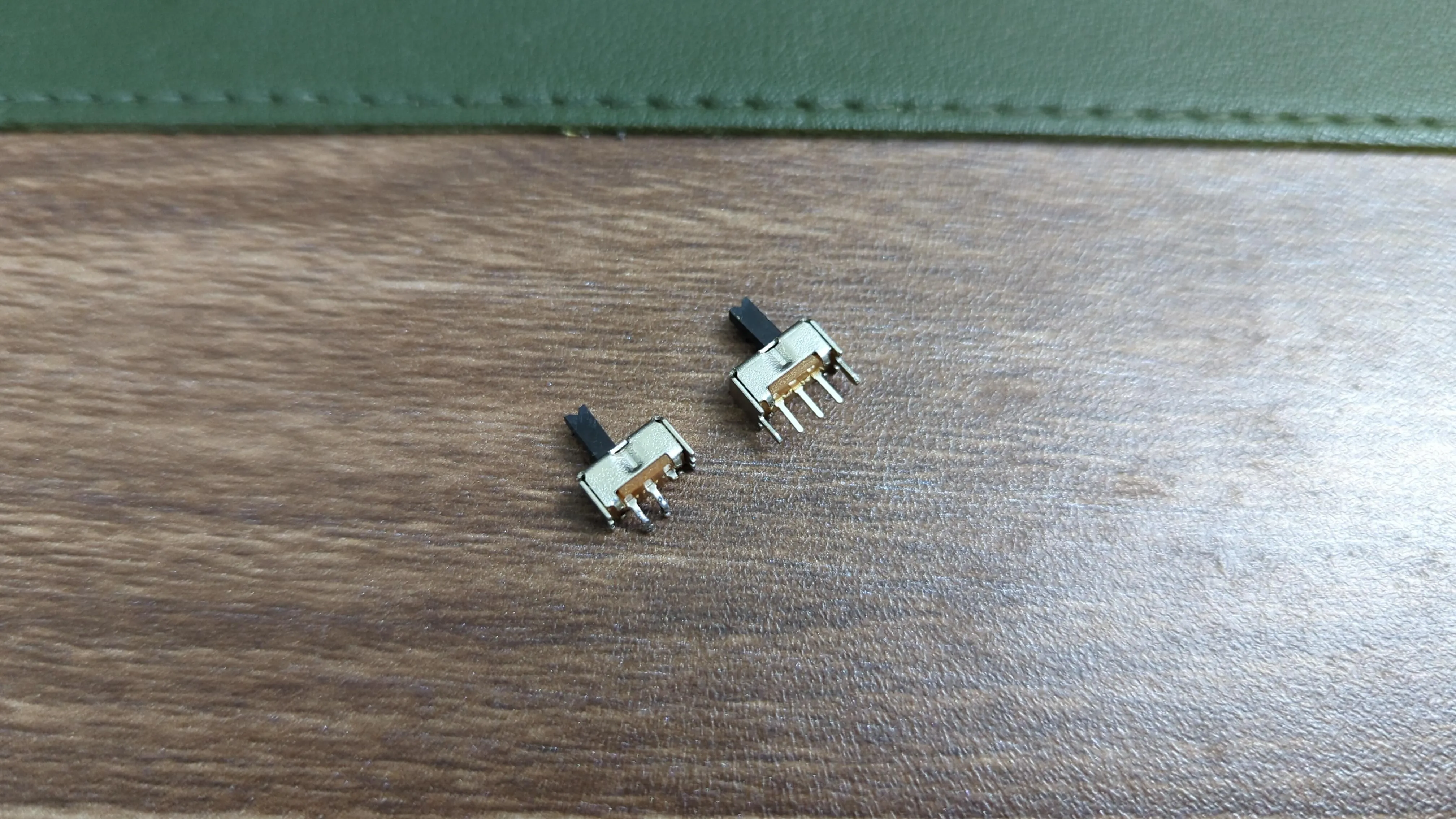
First of all, I cut off one leg of the 3-pronges switches, since you only need the center leg and one of the 2 side legs. It will look like this, specifically the one on the left.
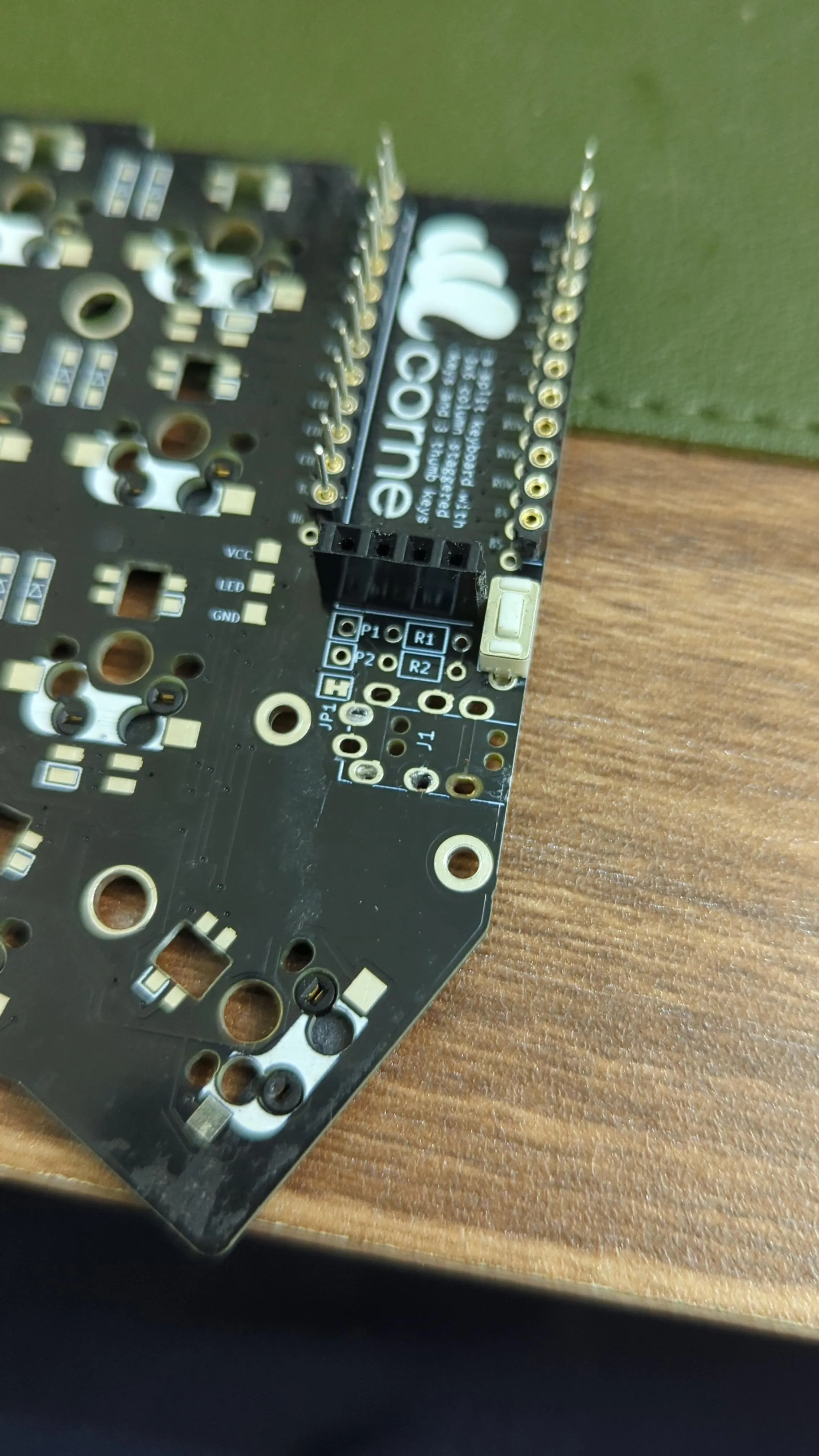
After that, I desoldered the TRRS ports so I can place the battery switches there. (I know it looks horrible, but hey, it works!)
For the next step, I push the battery switch legs through 2 no-pad holes on the pcb, then the ground wire (the black one) through the hole for TRRS ground leg, soldered it on the other side, then the power wire (the red one) through one of the hole, any one will do. (Ignore the hot glue, I need it to hold the battery switches in place, and I only add it after I finished soldering everything)
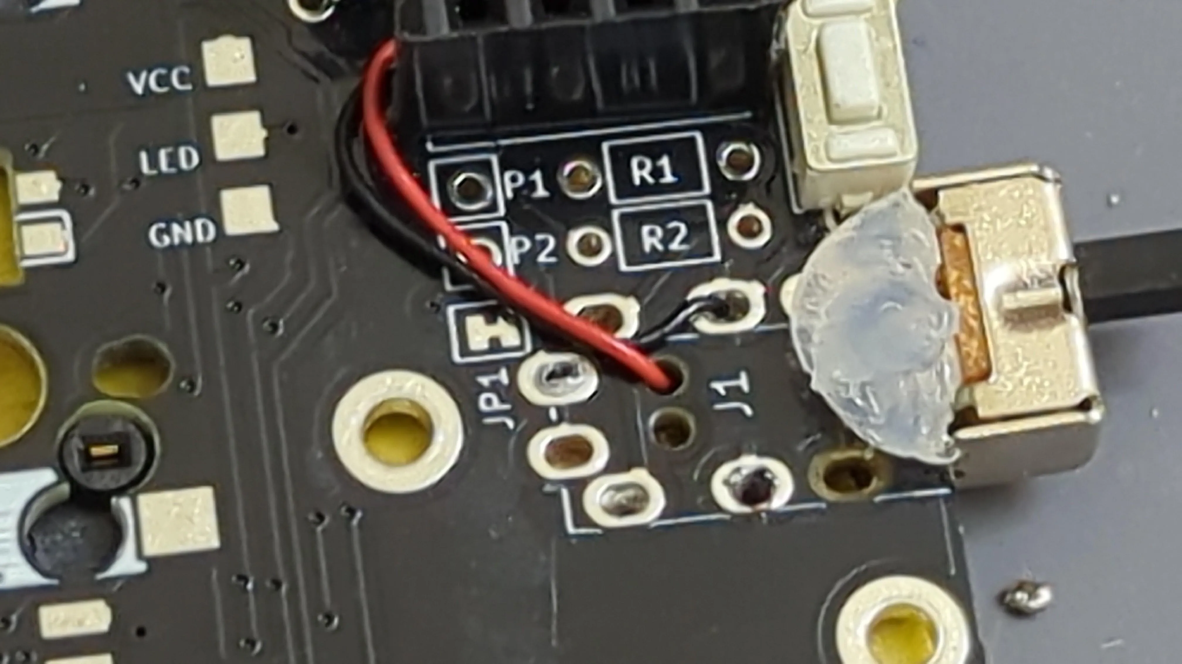
I then soldered the power wire to the center leg of the switch, then a bog wire to connect the other leg to the RAW leg of the controller. I use a piece of Teflon tape here to prevent any short from happening, you might not need it if you’re good enough.
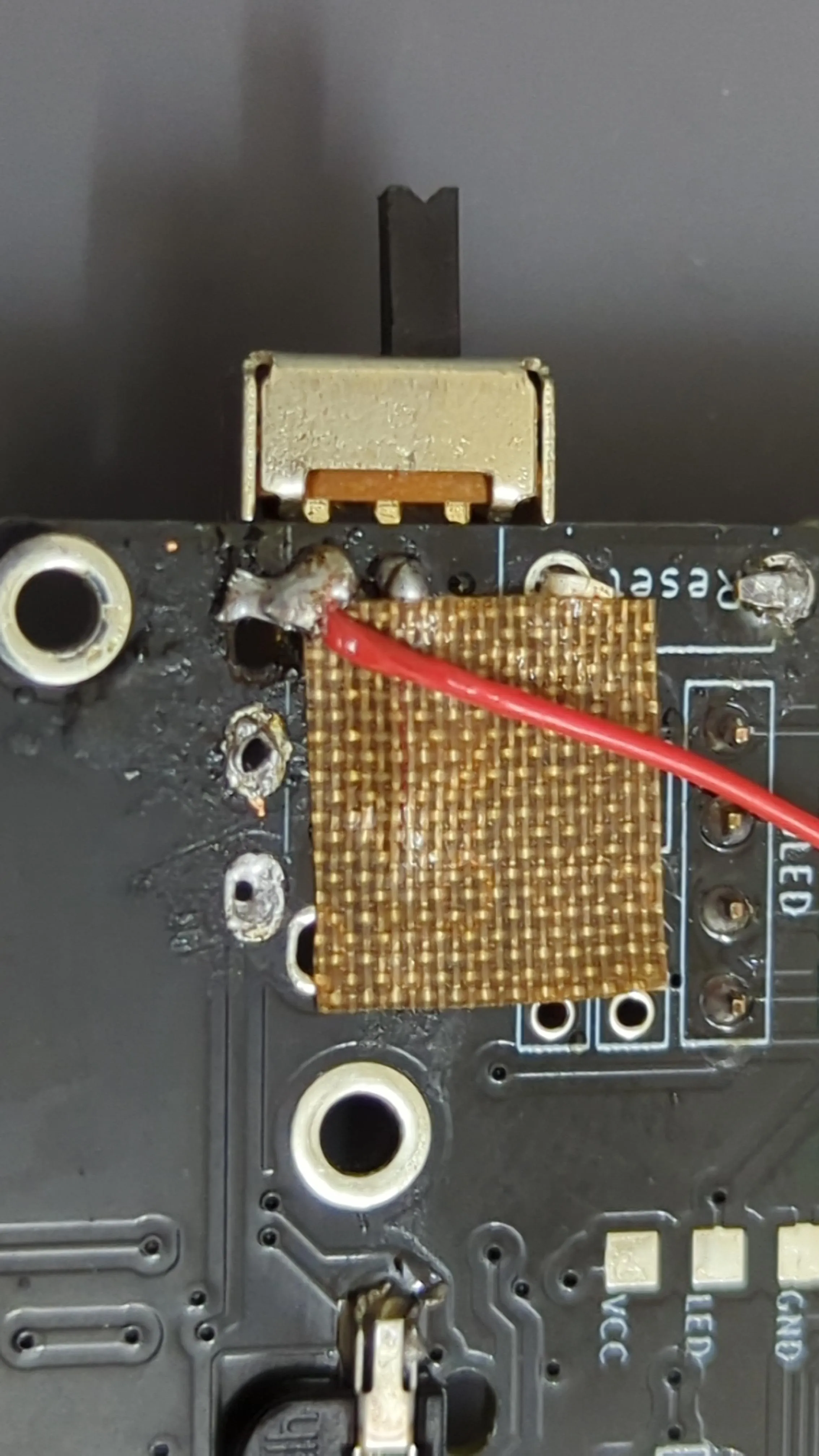
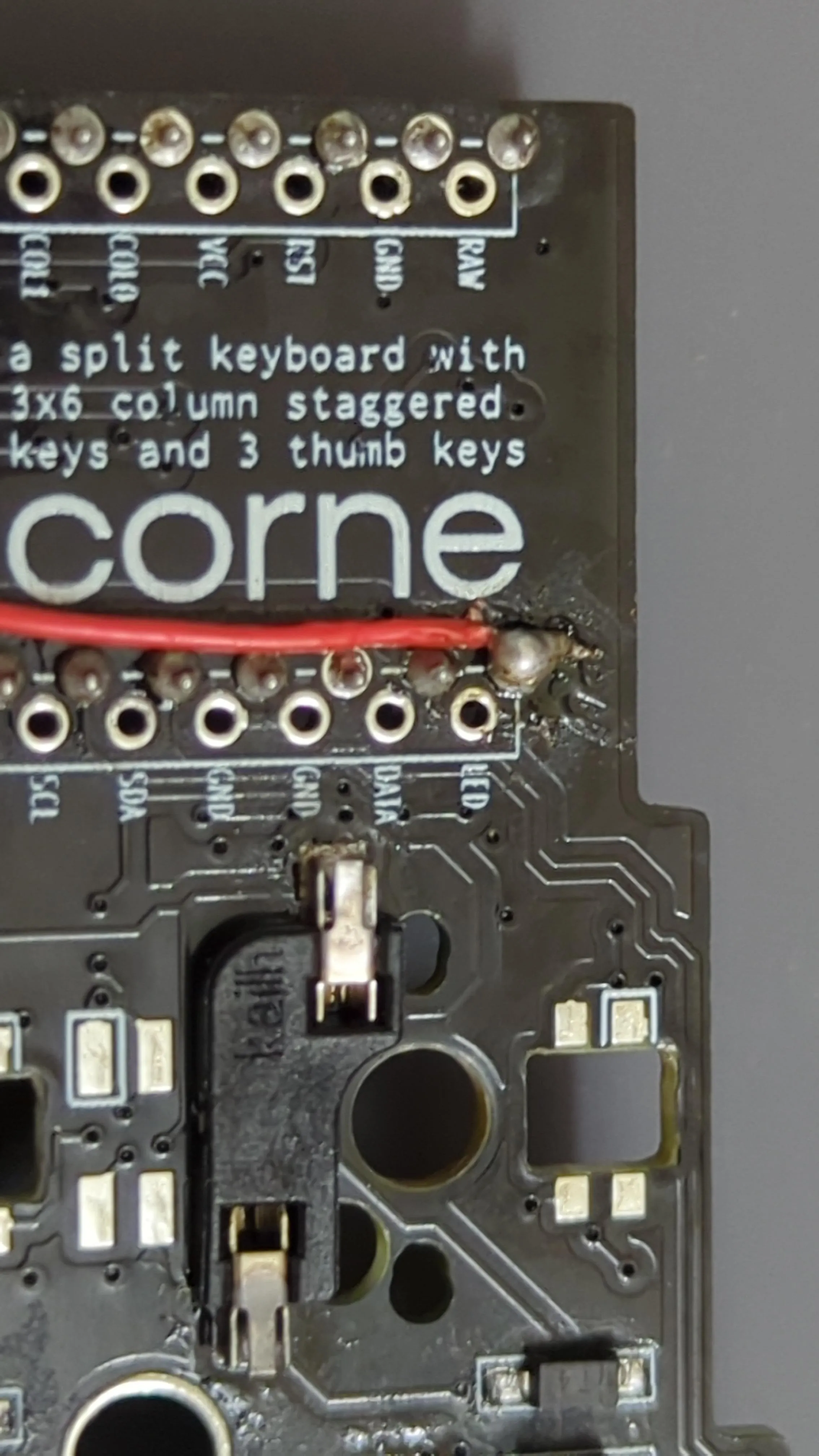
The hardware part for the keyboard is done! Now, we’ll move on to
The Dongle
You only need to read this part if you plan to use your dongle with an oled screen, otherwise, just move onto the next part.
So what you need to do is to connect the VCC and GND legs of the oled screen to the VCC and GND pins of the 3rd controller, then the SDA leg to the 017 pin, and the SCL leg to the 020 pin, that’s it!
How to put the dongle into the case? You’ll figure it out yourself, I believe in you! ;) Oh but do not put the dongle in it’s case just yet, you need to do the next step before that.
The Software (ZMK)
I’m lazy, so I just fork this repository from @mctechnology17, edit the keyboard layout with keymap-editor, enable Github Action, and Github Action will compile the software for the dongle and both side of the keyboard.
For the flashing process, I need 3 USB-C cables to ensure that all 3 of the controllers are connected right after flashing. To enter the bootloader of the SuperMini NRF52840 you need to short the RST pin on the controllers twice, on the keyboard, just click the reset button twice, on the dongle, you CAN solder a reset switch there, but I just use a tweezer to short the pin, but I have a trick so that you’ll only need to do this once for the dongle.
For more detailed instruction on how to flash the firmware, read this guide, since the SuperMini NRF52840 is just a more affordable clone of the Nice!Nano v2.
Because I use a 3rd SuperMini NRF52840 as a controller, I’ll need the file named “nice_corne_dongle_pro_micro_dongle_display” for the dongle, then the “nice_corne_left_peripheral” for the left half, and finally the “nice_corne_right” for the right side. If you don’t want the dongle, use the “nice_corne_left” for the left side instead, and you’re good to go!
Tips
-
Contrary to what is written on the ZMK repo I forked, macros are executed on the peripheral then send to the master. Instead, what always executed on the master side are called combos. So if you want to put the dongle into bootloader mode without soldering a dedicated reset switch or shorting the board with a tweezer, create a combos reference to &bootloader keypress.
-
Use &out keypress to switch between USB output and BLE output, this way you don’t actually have to connect the dongle directly to the PC, and can just connect it to a power source then connect to the PC via BLE.
What’s next?
That’s it, for now at least, until I get my hand on the Nice!View displays. I hope this post will help you guys somewhat if you’re stuck with a Corne Classic pcb and want to make it wireless like me.
I’m happy with the final result, now I can use my keyboard without the cable getting in the way, and I can even use it with my tablet (if I have one) or phone, neat!
The End
That’s it for this post, I hope you guys enjoy it, and I’ll see you in the next one. Goodbye and stay safe out there!